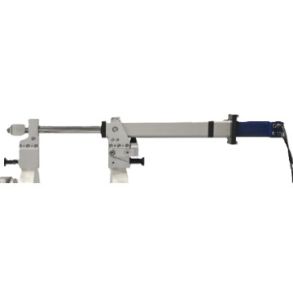
Load-holding valve for hydraulic weight compensation on Hürner Butt welding units

Connection via 1/4" hydraulic quick-connect couplings Recommended for hydraulic weight compensation up to 60 bar. Supplied in robust plastic case Counterbalance Valve for Hydraulic Butt Welding Description, Intended Use In butt welding with a heating element, the net weight of a component clamped into the movable carriage of a hydraulic machine chassis positioned vertically can bias the applied pressure. In particular, the carriage may start to move of its own when the pressure in the hydraulic circuit is meant to keep it in a stable position. The product is an adjustable counterbalance and load‑holding valve that is set between the hydraulic unit and the machine chassis and that, during pressure increase or decrease in the work flow, balances the load exercised by the weight of the component. The valve does not change any precautionary or risk assessment. All messages on (occupational) safety that apply to the butt‑welding system itself and to its use, apply unchanged when the load‑balancing valve is added while using it. Instructions of Use Adjust the valve as follows. The adjustment of the load to hold has to be performed for every single component/ welding operation. 1. According to the imprinted lettering, connect the valve to the hydraulic and control unit („Controller“) and the basic machine chassis („Machine“). Turn the knurl on it clockwise (towards “+”) as far as it will go. 2. Set the machine chassis up in the vertical position required for the upcoming welding operation and clamp the component to be processed into its movable carriage. In the vertical position, this carriage will be located in the upper position. 3. Using the controls provided on the hydraulic and control unit, move the movable carriage apart to the maximum. Then, turn the knurl on the load‑balancing valve carefully counter-clockwise (towards “–”) until the movable carriage starts to slip down. 4. At that point, turn the knurl in the opposite direction (towards “+”) for about one quarter of a rotation. The valve is now properly adjusted and ready for the upcoming welding operation. 5. Disconnect the hoses from the valve only when the pressure in the hydraulic circuit was already relieved at the end of the last welding operation. Maintenance Keep the valve and the coupling connectors of the hydraulic hoses clean. Clean them after use as needed. Apart from this, the product does not require maintenance. Technical Specifications Dimensions of valve 100 × 90 × 175 mm Dimensions, incl. hanging bracket 165 × 165 × 195 mm Weight 4,6 kg Max. operating pressure 200 bar Operating pressure of bias 60 bar Length of supply hoses from hydraulic unit approx. 950 mm

Model/Product no.: 514.541
Stock status: Ready for shipment!
